Santiago - 5-8-2011 at 08:59 AM
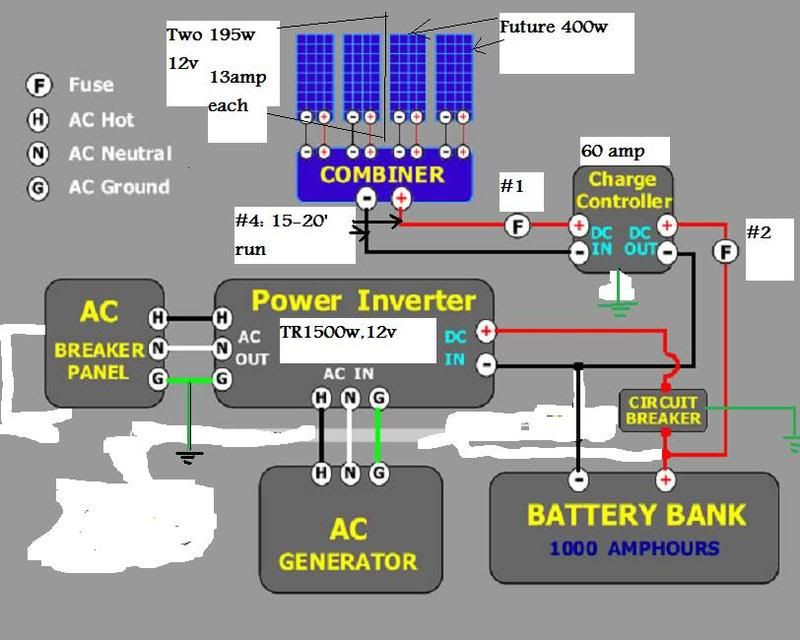
Here's a drawing of my simple set-up; remember that this is in a small cabin that will be used for 6-8 days at a time, about 4 times a year.
[img] [/img]
Notice that I start with two 195-watt, 13amp panels but will eventually expand to four: the charge controller and the inverter are sized to handle
that. My question on this thread is switching and fusing. I am a putter-arounder sort of guy and hate to spend a lot of money on off-the-shelf stuff
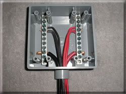
for the 4kw system designs NOB: for example, this is my PV combiner box w/ #6 from the panels and #4 to the charge controller:
[img] [/img]
A simple exterior box with a grounding buss cut in half and a cover plate and for about $10 I've got it.
I do not want to buy a Midnite Solar or Xantrex DC disconnect for $200+.
1: I'm thinking of using in-line maxi fuses for fuses #1 and #2: any issues or recommendations for these?
2: Is a disconnect or switch between the panels and CC really necessary; and if so, what do you use (remember, this will eventually carry about 60
amps if I stay at 12v). I can get switches from the auto supply stores cheaper, by a long shot, than from solar supply sources.
3: For the "Circuit Breaker" in the drawing, I'm thinking of using a Perko switch and a 150amp fuse that sits on the battery terminal that is often
used in marine applications (I am using 2/0 wires for battery connects and to the inverter). Suggestions here will be appreciated as I only know A/C
and am uncomfortable with D/C. Note: All 2/0 runs will be under 5' - fer sure.
4: Grounding has really got me confused: can I use the grounding buss in the A/C panel for the inverter and the CC? In other words, can I have one
grounding rod that everything, the PVs, the CC, the inverter, the load center is all tied to? If so, I'm thinking of putting a grounding buss on my
make-up board, a 4'X4' piece of plywood, bond that to the load center buss and have one run to the ufer ground. By the way, per Bob and a few others,
I am not bonding the neutral buss to the ground buss in the load center.
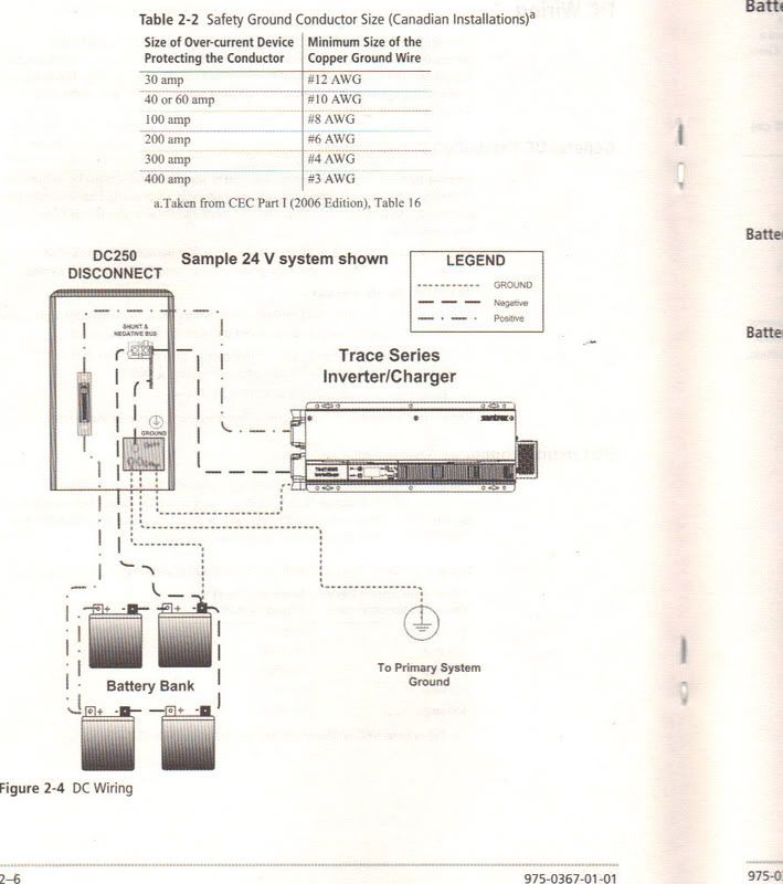
5: I do not quite understand this drawing: the perko switch and the fuse in #3 above takes care of the breaker in the positive run; but what is the
shunt doing? It looks like it's just a pass-thru to me and the negative and grounding busses are bonded together. Why is the hair on the back of my
neck standing up?
[img] [/img]
[Edited on 5-8-2011 by Santiago]
wiltonh - 5-8-2011 at 09:48 AM
I looked over your drawing and here are a few comments.
1. The Maxi fuse looks okay as long as you size it large enough. Remember the fuse is really there to protect from a short such as dropping a tool
into the equipment. You do not want a fire. I purchased fuses with tabs similar to large automotive fuses. They work but are not covered as well as
the Maxi fuses.
2. You do not need a disconnect switch but if you do not want one, Harbor Freight has a battery switch for less than $10 that would probably do the
trick.
http://www.harborfreight.com/heavy-duty-battery-cutoff-switc...
3. You could use a circuit breaker or another fuse. The fuse would probably be cheaper.
4. Yes you need only one ground. Your diagram looks fine to me.
5. The shunt is added so that you can use an amp meter to measure the current flowing in the cable. It is a very low ohm resister. There will be a
very small drop across it which is measured by the meter.
I looked over the specs on the other equipment and they look good.
The inverter you have chosen has its own transfer switch built in. This switch connects the input to the AC generator or the battery depending on
what is needed. The internet price looked to be almost $1000. That is expensive for a 1500 watt modified sine inverter. I believe Costco sells a
similar inverter without the switch for less than $100. You could choose to switch from battery power to AC generator by hand and save a lot of
money.
Unless you purchase a generator with an auto start feature, you are really doing the transfer manually anyway.
monoloco - 5-8-2011 at 09:56 AM
I believe the neutral and the ground need to be bonded in one place in the system, in my system they are bonded in the Midnite Solar E-panel. It came
wired that way, I assume they knew what they were doing.
Bob and Susan - 5-8-2011 at 11:26 AM
that combiner box exposes all your panels
you've tied them all together
one goes they all could go
that's why a combiner box has fuses (or breakers) for each set of panels
midnite combiners are on ebay for $100 bucks
you NEED a 60 amp single pole breaker from the combiner box to the controler box
i suggest you put it near the controler
do not bond the ground and the common in the inverter
it'll fry
it's very picky what it wants and gives out
do not buy ANYTHING from harbor freight for this project
do not use a perko switch
they are for cars and boats
not very reliable and could fry you equipment which is EXPENSIVE
you also NEED a 250 amp breaker from the batteries to the inverter
you need to ground the panels (tie together) then to the ground
you need to ground the controler (threre is a spot in the inverter)
you need to ground the inverter (there is a spot in the controller)
the #4 will work but it must be stranded
not a single wire
oh yea
try to keep your solar equipment the same
if you have 195's then stick with that
you don't want to "confuse" you delicate equipment
it's too expensive to replace
bkbend - 5-8-2011 at 12:19 PM
What Bob (or Susan) said. I did the pieces myself like you are doing (and ended up spending almost enough to buy the midnite solar E-panel), and here
are a couple parts Bob mentioned which I got from Arizona Wind and Sun.
FB-250T 250 amp fuse with FB250T 1 46.43
holder, Bolt Terminals
the bolt terminals will fit 2/0 with 3/8 ring terminal to fit between batteries and inverter.
Midnite Solar Baby Box MNBABYBOX 2 28.80
Enclosure for 1-4 Din
Rail Breakers
Midnite Solar MNEPV 150 MNEPV-00 1 11.50 Specify Breaker Size = AB-63
VDC Solar Array Breakers (MNEPV63) 63 Amp
I've got one box with a breaker for each side of of the controller (#1&2 in your diagram.
One other thing I added was this (NEC requirement):
80 amp 125VDC DC Ground MNDC-GFP80 1 55.20
Fault Protector
Here is Midnite Solar's explanation of what this does -- http://www.midnitesolar.com/pdfs/DC%20Ground%20Fault%20Prote...

 [/img]
 [/img]
 [/img]